NSCHRP-22 modular pumping station on common frame
Complete modular pumping station on common frame with cascade operation and frequency converter
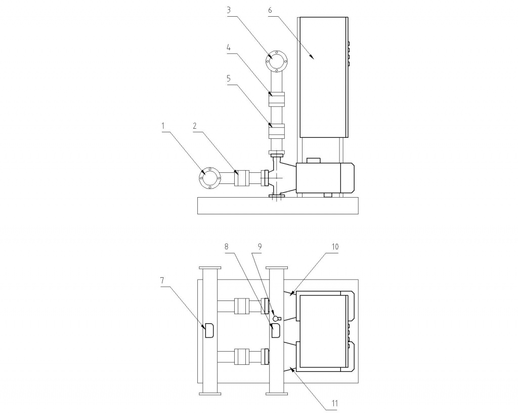
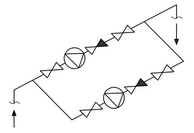
Product componentsThe pumping station is a modular system (Fig. 1), with all the necessary components being mounted on a common frame to fulfill the functional purpose of the product: Pumps, gate and check valves, intake and discharge manifolds, control cabinet, pressure sensor, and signalling gauges for protection against dry running. The hydraulic circuit diagram of the pumping station is shown in Fig. 2.

1 - intake manifold;
2 - gate valves;
3 - discharge manifold;
4 - gate valves;
5 - check valves;
6 - pumping station control cabinet;
7 - intake manifold signalling gauge;
8 - discharge manifold signalling gauge;
9 - pressure sensor;
10 - P2 pump;
11 - P1 pump.

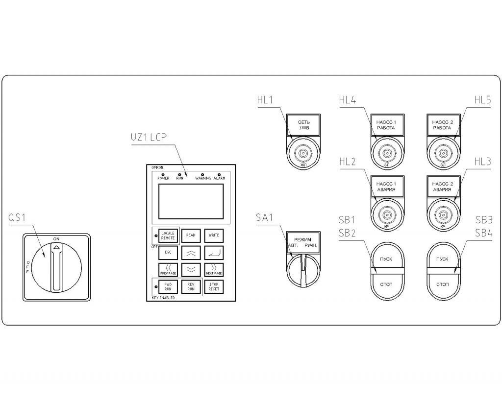
The pumping station control cabinet is designed as a metal board with a door on the front side and a mounting panel inside the enclosure. The controls are located on the door. Arrangement of the controls and light signalling hardware on the front panel of the control cabinet is shown in Fig. 3.

HL1 - 380V Power yellow lamp;
HL2 - Pump 1 Alarm red lamp;
HL3 - Pump 2 Alarm red lamp;
HL4 - Pump 1 Operation green lamp;
HL5 - Pump 2 Operation green lamp;
QS1 - Power ON/OFF switch-disconnector handle;
SA1 - AUTO/MAN Mode selector switch;
SB1 - Pump 1 Start button;
SB2 - Pump 1 Stop button;
SB3 - Pump 2 Start button;
SB4 - Pump 2 Stop button;
UZ1.LCP - Omron RX frequency converter control panel.
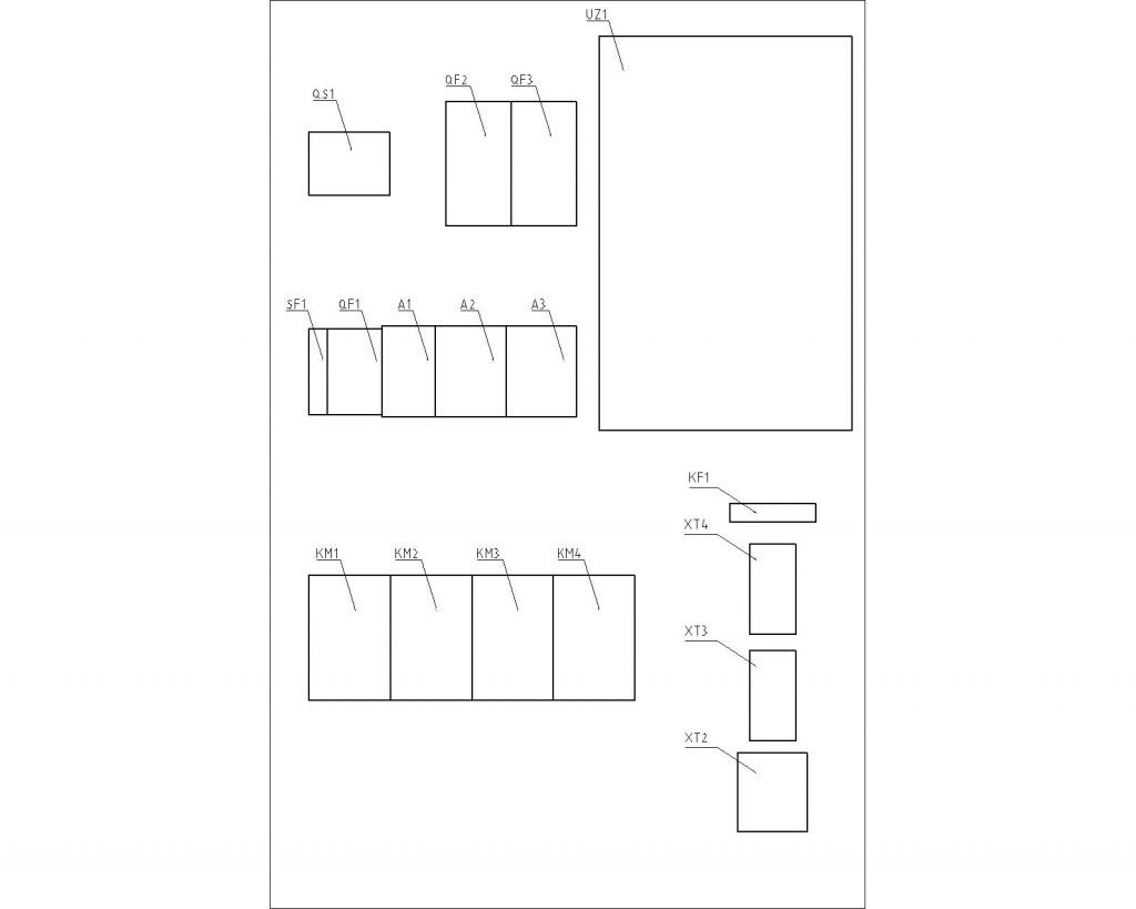
The following critical components are located on the mounting panel inside the pumping station control cabinet:

A1 - power unit =24V; 1.3A;
A2 - Siemens Logo! 12/24RC programmable controller;
A3 - Siemens Logo! DM16 24R expansion module;
KM1 - magnetic starter (pump 1 operation - via a frequency converter);
KM2 - magnetic starter (pump 1 operation - directly);
KM3 - magnetic starter (pump 2 operation - via a frequency converter);
KM4 - magnetic starter (pump 2 operation - directly);
KF1 - phase control relay;
SF1 - control circuit breaker;
QF1 - frequency converter circuit breaker;
QF2, QF3 - pump motor circuit breaker;
QS1 - Power ON/OFF switch-disconnector;
UZ1 - Omron RX frequency converter;
XT2 - Terminals for connecting power cables of pump motors;
XT3 - Terminals for connecting external signal conductors;
XT4 - Terminals for connecting signal conductors of the equipment located on the control cabinet door.
On-site equipment:
BP1 - Danfoss MBS3000 pressure sensor, 0-10bar, 4-20mA;
S3, S4 - DM2010SgU2 signalling gauge, 0-10kg/cm2;
M1, M2 - Pedrollo F50/200AR pump, 22kW, Q=103m3/h, H=56m.
Operating principle of pumping station with frequency converter
The pumping station ensures water supply in the water supply system with a set pressure regardless of consumption. Pressure is maintained by means of the integrated frequency converter according to a signal from the analog pressure sensor. Regulation is carried out in a steady, stepless and smooth manner.
The frequency converter is used for automatic regulation of the pump capacity. When it is necessary to increase the pump capacity, the frequency converter increases the pump speed, and when it is necessary to reduce the pump capacity, the frequency converter reduces the pump speed.
Pumping station installation and precommissioning
Mechanical installation
Install the pumping station at the place of operation.
Connect the intake and discharge manifolds to the water distribution system.
Electrical connections
Connect the pumping station frame to the existing ground loop. The grounding conductor cross-section should be at least 16 mm2.
Connect the external conductors according to the electrical circuit diagram.
Turn on the circuit breakers.
Feed the supply voltage (380V) to the control cabinet.
Perform a trial run of the pumps to ensure that the impellers are rotating in the right direction (direction of rotation is indicated by the arrow on the pump housing). The right direction of rotation is clockwise if viewed from the motor fan side.
Operation of pumping station with frequency converter
1. Feed the supply voltage to the control cabinet by turning QS1 isolating switch handle clockwise to ON position (Fig. 3). HL1 lamp (380V Power) will light up.
2. Select the desired pressure setpoint on UZ1.LCP frequency converter panel. F001 parameter is used to adjust the pressure setpoint within the range from 0.00% to 100.00% (0.00% corresponds to a pressure of 0kg/cm2, and 100.00% corresponds to a pressure of 10kg/cm2). The current setpoint value is shown in the bottom line of the panel display. To change the pressure setpoint:
- Press Enter (yellow button) twice. F001 parameter will become editable (with dark background);
- Use Left Arrow and Right Arrow to select the digit to be modified (integers, decimals, etc.);
- Use Up Arrow and Down Arrow to change the selected digit value;
- Press ESC to complete the operation.
3. Set SA1 selector switch (Mode) to the left position (AUTO). The pump will be started. HL4 lamp (Pump 1 Operation) or HL5 lamp (Pump 2 Operation) will light up. The station will start operating in automatic mode.
4. Set SA1 selector switch (Mode) to the middle position to disable the station (to stop the pump).
5. If any emergency or malfunction of the frequency converter or pressure sensor is detected (it is impossible to start the equipment in automatic mode) or the pumping station is to be used for extinguishing a fire, the pumps can be started directly in manual mode. In this case, pressure is not controlled, and the pump/pumps operate(s) at full capacity without a frequency converter. Manual mode is used only under control and responsibility of the operating personnel. Set SA1 selector switch (Mode) to the right position (MAN) and press SB1 button (Pump 1 Start) and/or SB3 button (Pump 2 Start) to start the pumps in manual mode.
Press SB2 button (Pump 1 Stop) and/or SB4 button (Pump 2 Stop) to stop the pumps in manual mode.
Description of electrical circuit diagram of pumping station control cabinet (with frequency converter)
The electrical equipment of the pumping station is powered by a three-phase 380VAC network.When QS1 incoming switch-disconnector is set to ON position, the supply voltage (380V) is simultaneously fed to:
- KF1 phase control relay;
- QF1 frequency converter circuit breaker;
- QF2 and QF3 pump motor circuit breakers;
and 220V is simultaneously fed to:
- HL1 lamp (Power);
- SF1 control circuit breaker.
When QF1 circuit breaker is turned on, 380V is supplied to the power terminals of UZ1 frequency converter.
When QF2 motor circuit breaker is turned on, 380V is supplied to KM2 magnetic starter.
When QF3 motor circuit breaker is turned on, 380V is supplied to KM4 magnetic starter.
When SF1 circuit breaker is turned on, 220V is fed to:
- A1 power unit (output voltage of 24VDC);
- Power supply of Q1, Q2, Q3, Q4, Q9, Q10, Q11 and Q12 relay outputs of A2 programmable controller.
=24V is fed from the output of A1 power unit to:
- Power supply of A2 controller and A3 expansion module;
- QF2.K and QF3.K auxiliary contacts of the motor circuit breakers;
- SA1 selector switch (Mode);
- KM1.K1 and KM3.K1 auxiliary contacts of the magnetic starters;
- S3 and S4 signal contacts of DM2010 gauge.
If the supply voltage is present at the power terminals of UZ1 frequency converter:
- UZ1.LCP frequency converter control panel starts operating (lighting);
- =10V is fed from the integrated power unit of the frequency converter to BP1 pressure sensor;
- =24V is fed from the integrated power unit of the frequency converter to the power supply of Q5, Q6, Q7 and Q8 relay outputs of A2 programmable controller.
If QF2 motor circuit breaker is turned on, =24V is supplied through QF2.K signal contact to I1 discrete input of A2 controller.
If QF3 motor circuit breaker is turned on, =24V is supplied through QF3.K signal contact to I2 discrete input of A2 controller.
Pump start in automatic mode (via frequency converter)
When SA1 selector switch (Mode) is set to the left position (AUTO), =24V is supplied to I3 discrete input of A2 controller. This triggers initialization of the pump start via a frequency converter (P1 pump start sequence is described below, with P2 pump being started in the same way):
1) Q1 relay output of A2 controller closes and 220V is supplied through KM2.K2 auxiliary NC contact (protection against simultaneous activation of KM1 and KM2) to the coil of KM1 starter.
2) =24V is supplied through KM1.K1 auxiliary NO contact to I13 discrete input of A2 controller (to check that KM1 has closed).
3) Q5 relay output of A2 controller closes and =24V is supplied from P24 terminal of the frequency converter to FW terminal of the frequency converter (frequency converter start signal).
4) After the frequency converter has been started, =24V is supplied from its discrete output (terminal 14) to I10 discrete input of A2 controller (to check that the frequency converter is operating).
5) Q11 relay output of A2 controller closes and 220V is supplied to HL4 lamp (Pump 1 Operation).
P1 pump is operating in normal mode.
Pump stop in automatic mode (via frequency converter)
When SA1 selector switch (Mode) is set to the middle position (0), =24V is withdrawn from I3 discrete input of A2 controller. This triggers initialization of the pump stop via a frequency converter (P1 pump stop sequence is described below, with P2 pump being stopped in the same way):
1) Q5 relay output of A2 controller opens and =24V is withdrawn from FW terminal of the frequency converter (frequency converter stop signal).
2) =24V is withdrawn from the discrete output of the frequency converter (terminal 14) and, as a consequence, from I10 discrete input of A2 controller.
3) Q11 relay output of A2 controller opens and HL4 lamp (Pump 1 Operation) goes out. P1 pump has been stopped.
4) Q1 relay output of A2 controller opens and KM1 magnetic starter becomes inactive.
5) =24V is no longer supplied through KM1.K1 auxiliary NO contact to I13 discrete input of A2 controller (to check that KM1 has opened).
P1 pump has been stopped.
Pump start in manual mode (directly)
When SA1 selector switch (Mode) is set to the right position (MAN), =24V is supplied to:
- SB1 button (P1 Direct Start);
- SB2 button (P1 Direct Stop);
- SB3 button (P2 Direct Start);
- SB4 button (P2 Direct Stop);
When SB1 button (P1 Direct Start) is pressed, =24V is supplied to I4 discrete input of A2 controller and P1 pump is started directly (without a frequency converter):
1) Q1 relay output of A2 controller closes and 220V is supplied through KM1.K2 auxiliary NC contact (protection against simultaneous activation of KM1 and KM2) to the coil of KM2 starter.
2) =24V is supplied through KM2.K1 auxiliary NO contact to I14 discrete input of A2 controller (to check that KM2 has closed).
3) Q11 relay output of A2 controller closes and 220V is supplied to HL4 lamp (Pump 1 Operation).
P1 pump is operating in manual mode.
Pump stop in manual mode (directly).
When SB2 button (P1 Direct Stop) is pressed, =24V is withdrawn from I5 discrete input of A2 controller and P1 pump is stopped:
1) Q1 relay output of A2 controller opens and KM2 magnetic starter becomes inactive.
2) =24V is no longer supplied through KM2.K1 auxiliary NO contact to I14 discrete input of A2 controller (to check that KM1 has opened).
3) Q11 relay output of A2 controller opens and HL4 lamp (Pump 1 Operation) goes out.
P1 pump has been stopped.
These sequences can also be used to start and stop P2 pump in manual mode.
